
This is going to be a biggie. I'll be containing my full flow of work in this post.
Over the summer, certainly off the back of my last project detailed in this blog, I’ve been turning around in my mind the concept of expanding from a single planet. Typical of my imagination, the task I envisioned wasn’t particularly on a small scale.
I want to make the universe.
Over the summer, certainly off the back of my last project detailed in this blog, I’ve been turning around in my mind the concept of expanding from a single planet. Typical of my imagination, the task I envisioned wasn’t particularly on a small scale.
I want to make the universe.
A procedurally generated one mind; I neither have the time, experience nor, really, the knowledge to recreate the actual universe. Also, given that there are already experts trying to achieve such a feat, I’ll leave it with them.
Instead, I want to create a universe that abides to my own defined rules.Minecraft has a deep seeded enticement for me where I’m happy to spend literally hours moping about the land, cave exploring or mining for ores to help build better tools to… mine some more. The attractive element, for me, is the fact it’s randomly generated; no one has hand crafted the level I’m exploring, and I find that interesting.
Another big interest in my life is Astrology and Cosmology. Since I was little I’ve always had a keen interest in the ways of the Cosmos. Which was what caught my attention the first time when I was looking around at procedurally generated terrains; a landscape wasn’t big enough, I wanted to orbit the planet. Now, I want to explore the universe!
The concept stuck securely in my mind is this: The universe will contain a number of galaxies. Each galaxy will then contain a number of stars. Each star will have a system formed around it.
Obviously for such a big task, there needs to be some form of compression as no typical computer could store such large data. Instead, taking a leaf out of Minecraft's book, the break down of the parts that will make up the universe will be based off a seed which will dictate the bearings for the galaxies and also how the suns that form each galaxy form around the galaxy and similarly, what each solar system looks like.
This will allow me to represent objects that are out of rendering view with a point (a ‘star’ if you will) in the distance. When travelling through, multiple coordinate systems can be used to simulate where the user is, relative to the solar system, galaxy and the universe in general.
Of course, I was under no illusions that the concept I had thought of was unique and original, I was sure there’d be some other geeks out there with a taste for space and a knack for coding.
As expected there was.
However, I was dismayed to discover just quite how good their work is.
Bloody Russians!
Space Engine is an amazing piece of software, recreating practically exactly what I envisioned, and yet in a more aesthetically pleasing manner than I believe is within my ability.
And this displeased me. I’m a rather pessimistic person, and as such, I don’t lie to myself about my work; if something’s shit, I don’t look for some redeeming aspect, I just acknowledge it isn’t good and try to work out how I can improve on it. However, when something is good, I’m ecstatic (or as close to such a feeling as I can conjure) and so naturally, something ‘good’ is what I always aim for.
Seeing Space Engine has unfortunately raised the bar on what I want my application to be like. I’ll be striving for greatness, but I’m going to be working my arse off trying to accomplish it!
I mustn’t take my mind off what this application’s primary aim is however, the aim of it is to prove… something. The approach I have taken is possibly backwards to that of most students.
The overall aim is to provide an answer, or attempt such, to a given research question, one which will allow me to write up a decent dissertation. The project is to provide evidence supporting such research.
Therefore, being so heart-set on this project idea, I must come up with a research question that could justify such a peculiar task. I was put mildly at ease upon bringing up such an issue with my Honours project head, who approved of both the scale and context of this project and mentioned that, while certainly I should be considering it, the question itself is not immediately important and it should come to me over time. Some truly thought provoking, spiritualistic advice.
I have some initial ideas for questions that both interest me and, more importantly, could provide a reasonable basis for taking this project on.
The first that I thought of was finding out how much control over a procedurally generated ‘world’ a creator can have. The rationale of such a question is down to the application of procedural generation in games. For example, on 20th May 2009, the driving game Fuel won the Guinness world record for the “largest playable area in a console game” for having 5560 square miles of land! Of course, this isn’t a modelled area as one so large could neither be built in a reasonable amount of time (even with AAA teams 900 strong!) nor would such an undertaking be economically viable and nor indeed, would such a world be storable on a single disk! Instead, the world is procedurally generated. The exact methodology of it is currently unclear to me, and could be one of my focal points for research as I could look at how they placed roads and other objects - thereby, how they controlled certain aspects of it so that it wasn’t completely volatile.
I was initially quite pleased and sure of such a question. However, the more I turned it over in my head, the less confident I was of it. So I thought deeper for a question and ended up on building off the old to come up with exploring the limitations of procedural generation, particularly within games. This would not only look at the previous question’s point of how much control one could have over a procedurally generated world, but also look at how large it could be.Fuel was unprecedentedly large but it was still finite. Minecraft is possibly endless (though the editing aspect may limit it to the amount of memory on the computer it is generated on!) however, there appears to be a threshold where after a certain distance, the land is generated in a peculiar fashion.
Such a point led me to consider what I would want for my own application. Initially I had envisioned a finite universe, one dictated by a texture (for instance, a turbulence texture, where values of 1 dictate a galaxy). I could then wrap the universe to the effect likened to Asteroids, where the user relocates when going out of the bounds of the texture. Would it be possible, I wondered, to instead have it completely based of some form of a hashing algorithm, determining the placement of galaxies (as mentioned earlier, defined by a ‘seed’) and therefore have a theoretically infinite universe?
While certainly an interesting avenue to explore. It could be difficult to implement over the original finite idea. It would also contradict the Big Bang Theory (though arguably, the edge of the galaxies are moving apart faster than the speed of light, as such should be technically unreachable); such a contradiction would hurt my inner astrologist! However, as a good source of researchable evidence, if this was to be my research question, it will probably be implemented.
As of yet, I’ve not been able to think of a better question that I would want to pursue. I’ve no doubt that, as I go along developing my idea, new discoveries will lead me towards a better question. Hopefully I don’t get lead astray and instead of converging on a solid concept, diverging erratically.
Which is almost what I do everytime I come across an article regarding the cosmos, or if I stumble across a technique I wasn’t aware of/didn’t initially understand. For example, I need to leave the urge to have bouncing light at the back of my mind (culprit) or almost ditching my initial plan for tessellated terrain on planets for voxels because I read and finally understood on method of doing them - and it sounds awesome!
Taking on such a big project will require a decent amount of planning on my part. In addition to this, if I don’t have such a plan which can intrinsically detail what I’ll do to achieve what I’m setting out to do, my idea will be either shot down entirely, or slated to be scaled back (most likely all the way down to a singular planet!)
So as an initial plan, what is the absolute basic application that I need running?
Multiple planets; each using varied shaders to create different effects such as a planet with an atmosphere, a planet with an active mantle and therefore tectonic plates (which lead to mountainous terrain) or a gaseous planet.
Generating such large bodies will require smart optimisations. The most apparent of which (besides typical frustrum culling) is level of detail (LOD) which will cut down on unnecessarily generated triangles. The fun aspect of this is the lack of experience in this area…
As such, I will need to research heavily into LOD and find out what techniques are suited to this application. An initial look into it shows that a lot are designed for terrains based off a plane. There aren’t many based on spherical LOD, but one implementation that appears most common is using a tree structure based on a unit cube and then mapping that cube to a sphere.
Decent lighting; the aim is to challenge the limits of procedural generation with a nod towards game design, therefore lighting is a must.
The most basic of which will be a directional light, which will mean I’ll need a host star!
Once directional lighting is implemented, more precise (and thereby more computationally expensive) lighting can be considered. The first of which would most likely be the recalculation of the vertex normals. This would make the landscape immediately more believable.
On top of that, I could look into different ambient occlusion lighting techniques to add to the realistic lighting. However, it is unlikely that I am going to develop a planet which generates caves (as I plan on utilising a fBm based multifractal, which generates mountains and valleys)
Going off these initial requirements, it could be conceived that a solar system would suffice for this project. However, if it’s possible to generate one solar system, it should therefore be possible to generate multiple ones, as no more than one would need to be rendered at a time (these systems are rather far from each other!)
Building off that notion; it should therefore be possible to generate an entire galaxy and from that my target of a universe. These distant celestial bodies can be represented by points once beyond a certain limit (most likely, the far plane). Which will conveniently render a star filled skybox.
Once I’m confident I’ve created an application that expresses the major capabilities of procedural generation, I can move onto rendering the more aesthetically pleasing and more advanced techniques.
As mentioned earlier, an atmosphere is a rather high up on the “polish” requirements. As it isn’t possible to use the typical skybox of a game, other techniques will need to be implemented to not only create a believable atmosphere while situated on the planet, but also while observing it from space. Creating a decent enough atmosphere should generate the ecliptic effects which tantalise my inner astronerd.
Another feature that I’m keen to have implemented is intelligent life. Naturally it’s been the focus of public interest for centuries (and with the advances in technology and knowledge, quite vigorously over the past few decades). I envision the planets in the application having statistical qualities accompanying them. Such data could be the size, whether the core is active (which leads to a body having a magnetic field and thus determines whether liquid water may be present on the planet) and whether there’s a mantle inbetween (which would result in the mountain ranges), how much of an atmosphere is present (which would determine how big of an impact meteors have on a planet and thus whether there are impact craters) etc.
Taking into account all this data, I could then have certain conditions leading to the inclusion of life on a particular planet. This could be from a simple geometric being to more divergent lifeforms (most likely generated through procedural modular design). The other aspect of this could be the likelihood of cities on a planet and their abundance (possible Star Wars influence on the go…) as procedural cities are another interesting avenue to me.
I’ve now built my (first) desktop computer. After various issues regarding exactly how components are hooked up and the long list of issues with Microsoft’s distribution efforts, I have been able to get my computer up and running.
Initial tests using the DirectX samples reveals that my computer is more than competent with high end rendering.
I also ran my previous procedural planet on it to find it not only runs (as expected) but even at the highest quality, it was pushing ~60 frames per second!
One issue I did encounter though is the wireless keyboard I’m using. ‘Optimisations’ in the keyboard lead it to stop a key press if held down for a long amount of time which meant moving the camera was rather jagged.
Now that I’m set up, I can begin making my framework for my Honours project.

Starting from scratch, I wanted to make sure my code wasn’t clunky from the get go. So my first step was to create a simple DirectX application (the most basic) with the windows API code and DirectX code moved out of the main file. This is never a straight forward task but fortunately the task was successful.
It was rather satisfying staring at a blank coloured screen.
It was rather satisfying staring at a blank coloured screen.
Visually, there would appear to have been no progress, but I am currently concentrating on creating the groundwork for my framework.
I have a timer for the application events to synchronise to implemented as well as a high-resolution timer which could be used to timing certain parts of code.
I was also beginning to create Vector and Matrix classes (well, actually I did finish my vector class). My initial thoughts were, as DX11 doesn’t come with a maths library, I looked around and there wasn’t really a solid consensus on which would be best suited. So I decided to create my own.
This served as a good revision of operator overloads and even the maths behind dot and cross products. However, I later decided to instead go with a bespoke library. I was going to go for XNAMath, as this appeared to be best suited to the application I wish to create. However, looking at MSDN, DirectXMath has apparently superseded XNAMath (along with other popular graphics based maths libraries) and so I have decided to go with that.
DirectXMath is rather recent (~March 2012) and is accessible through the Windows 8 SDK, which meant not only did I have to download the SDK, but I also needed to install the latest .NET framework as I am developing on a Windows 7 OS.
EDIT: perhaps too recent; the .NET framework update created a conflict for VS2010 which meant it would not compile. In addition, I’ve been unable to include DirectXMath.h unless I include the file path but then there are compilation issues.
As such, I will now instead revert back to using XNAMaths!
Next steps are creating a controllable camera class and then a simple 3D triangle that I can fly around to test the camera is working correctly and also get an initial framework for the rendering pipeline.
After multiple attempts to download and install Visual Studio 2010 Service pack 1, my project mercifully compiled successfully.
The thought of having to restart from scratch is never a comforting one. As such, I’ve been shocked into finally getting around to setting up an SVN.
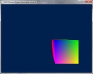
So close to being able to finish the basic parts of the framework. After some minor (and partially embarrassing) errors and… non errors, I have been able to get a 3D cube to render:
The embarrassing non-error was that it appeared that the cube was not rendering at all. After an initial mis-type error, I was left scouring my code for what could possibly be preventing the cube from rendering (as no run-time errors or warning were appearing to assist). It turned out, after holding the “move backwards” key for a prolonged period of time, that my preemptive assumption that heightening the camera would be beneficial when first making the camera was infact an incorrect assumption, the cube was indeed rendering, I was just too damn high to see it!
Now that I have a point of reference, I can go on to make my camera rotate and check it does so correctly.
On a non-code subject; I was also considering what games would be suitable for this application specifically as that will help determine what parts of the application to prioritise. Initially I was thinking about the exploration aspect and from that have the possibility of finding life determined by the planet’s aspects.
This was before I got around to looking at Elite. As Acknowledged previously with respect to the Space Engine program, I was aware that my desires for my application were not original. However I was more dismayed to discover the breadth of Elite and it’s space trading gameplay structure. It is an awesome game. It’s also three decades old.
Initially that was a negative thought. But then I thought about how it instead could lead to opening up the possibility for showing the improvements of technology. I’m in disbelief at what they packed into the game; it was certainly ahead of its time both technically and aesthetically, but what could a space game be like today.
Before I develop this idea, I am still rather set on the statistics of planets detailing whether there could be life. Instead of finding life, the object could be instead the player analysing a planet and determining if it could serve as a good settlement for a colony.
After creating a cube class and moving the code for creating a cube into said class (and checking that it ran), I was considering committing to the SVN. However, I was sure I’d be able to quickly add in a feature which would rescale the buffers when the window is resized. However when I began trying to implement this, I realised it wasn’t going to be as straight forward as I had planned (due to data being inaccessible etc) I decided to go ahead with trying to implement it and ended up in quite a mess yet still sure I’d be able to turn it around. Sadly I had to admit defeat. Sadly still, I reverted to the last update, which set me back numerous hours.
The moral of the story: even if it’s a small and seemingly insignificant change, still commit!
As well as moving the cube code into it’s own class, I managed to get a basic rotation matrix based on the y and x axis. This of course makes the camera susceptible to gimbal lock, but for the purpose of development, it suffices as a placeholder camera.
I’ve also improved the fps output on the console display, it updates every second with how many frames were rendered. (currently sits at around 12K which I suspect my monitor can’t quite keep up with)
I also want to add, for the benefit of anyone in a similar position to me that may stumble across this blog; .fx files are in high level shader language (HLSL) and therefore interchangable with .hlsl files. It’s clearly (from my looking around on the internet) assumed knowledge as no one seems to explicitly state such.
When I first started properly looking into DirectX11’s tessellation stages, I realised quite quickly that there aren’t a lot of tutorials available as there is for other parts of the API.
This had me slightly panicking as I feared I would be unable to keep to the implementation schedule that I have set myself to make sure I can accomplish the project’s aims.
The best tools I could find were a combination of the DX11 samples that are provided with the SDK (but which aren’t completely clear or simple) and the descriptions provided on MSDN (which also weren’t always clear).
Fortunately Rastertek has a tutorial which is as close to what I was looking for as I could get; going through the implementation process bit by bit. Unfortunately, that still isn’t enough for me to completely have an understanding of how the shaders work and their functions. It will take a bit of experimentation to help understand how the various parts interact with each other.
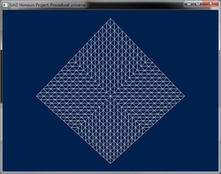
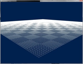
I have however been able to create a tessellated patch:
This had me slightly panicking as I feared I would be unable to keep to the implementation schedule that I have set myself to make sure I can accomplish the project’s aims.
The best tools I could find were a combination of the DX11 samples that are provided with the SDK (but which aren’t completely clear or simple) and the descriptions provided on MSDN (which also weren’t always clear).
Fortunately Rastertek has a tutorial which is as close to what I was looking for as I could get; going through the implementation process bit by bit. Unfortunately, that still isn’t enough for me to completely have an understanding of how the shaders work and their functions. It will take a bit of experimentation to help understand how the various parts interact with each other.
I have however been able to create a tessellated patch:
I was so relieved as I basically jumped from my cube rendering to this patch, adding in all the hull shader and domain shader code in one sitting. I couldn’t see another way of implementing this in smaller steps so took a leap and it payed off.
However, I do now need to spend time trying to understand exactly how it all works together as I have currently second guessed my way to the above grid.
There are multiple artefacts that are no doubt down to how the patch is implemented;
Firstly, I am unable to freely transform the patch. I can scale it successfully so the tessellation is more apparently, but other transforms such as lowering the y values results in the patch apparently not rendering (thought it could be moved far off screen or have all the backfaces facing the camera)
Similarly, I’ve had to use counter clockwise triangles as the patch was “upside down”
Finally, I added in noise to test out if I can displace the vertices, and this highlighted another issue; the vertices are rendering in an incorrect order, so some vertices which are behind others are being rendered ontop of them:
I feel the former issues might be easy to solve, however I’m not sure where to even begin solving the latter problem.
Still, getting a tessellated patch is back on track with where I expect to be, so I’m going to count my blessings.
After a few days of looking into the tessellation stages of DX11 I’m… still unsure on some things.
I’ve managed to create a patch which is centred around the single point I pass into the pipeline. I also currently only ever use 1 control point as I create the vertices based off this single point plus the vertex’s UV point.
One of the things I’ve yet to figure out, is why it seems to be a quarter of what I expect. For example, to make a 1 X 1 grid, I’d expect to offset each corner by 0.5 in the x and y (or z) position. However, this produces a patch that is 0.25 X 0.25.
The obvious fix for this, which I’m currently using, is just to offset by 2, which indeed does produce a 1 X 1 patch but I’m no sure why.
From a wireframe view, I can see that the patch itself is split into 4 parts, so I imagine this has something to do with it but I’m yet to piece it together.
Once I’d made the patch centre around the point I pass in, I was able to make a cube (again):
This cube showed that the rendering issues are a problem for within each individual patch as opposed to with each other. This issue can been seen by the picture below.
EDIT: sadly, there is still a rendering issue between patches. Hopefully, creating a depth buffer will help alleviate this issue.
As much as I wish to delve into finally creating a planet, it’s important that I try to resolve these rendering issues sooner rather than later.
I realised at one point that I may have gone about creating the cube the wrong way as it relied heavily on transformations around the origin. So I wondered what would happen if I moved the planet (as I intend to later down the line) the results were… interesting.
So I went about rewriting the cube creation code and added in a “position” vector which keeps track of the centre of the planet, which will come in handy when transforming the cube into a sphere.
I then test whether the cube could be moved around and the test was a success as the video shows; the cube remains such when moved about.
After avoiding my next planned step, to implement a depth buffer into my framework, I finally decided to go for it. I was avoiding it because I feared it was too simple of a fix, that I would get my hopes on the lack of depth testing being the issue. This was of course the logical problem, but I feared I’d implement it only for it to not work.
But I went for it and ran the added code with fingers crossed. Sadly, the cube wasn’t being rendered at all. Until I realised I wasn’t clearing the resource view for the depth stencil buffer. I figured this wouldn’t initially be an issue as I wasn’t moving however, once it was added in, the cube rendered and correctly so!
Now that issue is out of the way, the next step is..
Creating a sphere from my cube (and adding in spherical lighting)
The plan was to study the techniques for projecting a cube onto a sphere. However, one of the things I love most about coding is having a problem that I know I can over come. I know that I know how to transform a cube’s coordinates into spherical coordinates.
So I grabbed a piece of paper to jot down my thoughts.
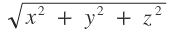
I have a point on an edge of my cube. I want to scale this point along the vector from the centre of the cube/sphere to make it a unit vector.
Therefore I need to divide through by the vector magnitude, which is the square root of the addition of each of the vector’s squared components.
Or in symbol form:
So I grabbed a piece of paper to jot down my thoughts.
I have a point on an edge of my cube. I want to scale this point along the vector from the centre of the cube/sphere to make it a unit vector.
Therefore I need to divide through by the vector magnitude, which is the square root of the addition of each of the vector’s squared components.
Or in symbol form:
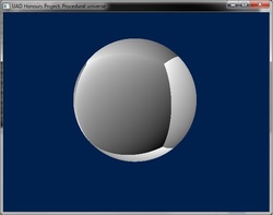
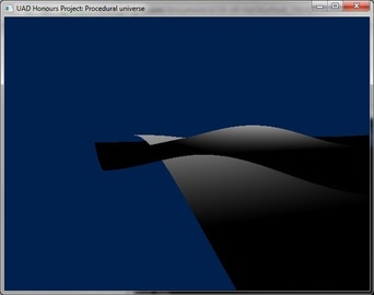
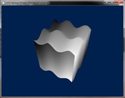
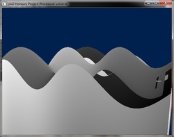
I tried this out and, to my satisfaction, this image was produced:
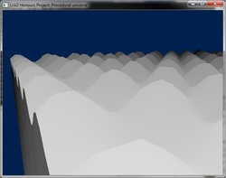
Also, with some quick fiddling about with the noise functions, I produced this:
Not quite mountains, but it clearly shows how displacing the vertices based on the noise function creates a seamless terrain.
It should be said that this probably won’t be the finalised algorithm for creating my sphere, I’ll certainly be adapting it so that it can again be moved around, scaled and rotated as a sphere.
In addition, it’s a simple approach to creating the sphere, using the costly square root function for every rendered vertex. There will be a more complex but more efficient manner to create the sphere from a cube, but it isn’t my primary focus yet.
The next steps involve making the tessellation dynamic - based off the distance from the camera - and making multiple patches on each face (in readiness for using octrees as a patch is created from a single point, I can make that point correspond to such on an octree).
I’m rather surprising myself at how far I’ve managed to get in just over 5 weeks, almost makes this mammoth project seem plausible.
I’ve enjoyed a dangerously long break but participating in the Scottish Game Jam ‘12 (and the Global Game Jam ‘13) has highlighted how important it is that I keep on top of my work.
The SGJ13 entry wasn’t award winning, but with the help of an artist we were able to produce a rather nifty looking project. I had to invest in more maths however to get a deceivingly simple feature into the demo. This drove my determination to overcome the problems in my honours project.
It won’t be easy getting back on top of things when there are so many issues to iron out. But I’ll have to take them out one by one.
I’m making some progress splitting up the faces.
I currently have it so you can specify how many times to split each face of a cube. Unfortunately I’m going to have to overhaul the cube code as it currently doesn’t work.
Equally annoyingly, I created an algorithm to position each patch of the face correctly to create the full face. The values created were seemingly correct. However, put into practice it didn’t seem to place the patches where I expected.
As is clear from the image, once the patches are properly implemented the amount of detail that can be on a big planet will be.. for lack of a better adjective, sexy.
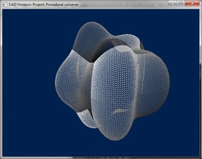
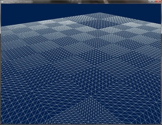
Similar to how the small change of making my cube to sphere work managed to open up a lot of opportunity, I have managed to get the side-splitting (not humorous) method to work.
Using my sun object to test it, I specified to the application to split the front face 3 times. The splitting method quarters the patches so splitting 3 times should give me 64 patches.
Each patch is only 16 by 16 (as the sun is spherical and doesn’t need too much detail) however, even only using 16 by 16 patches creates a lot of detail when split 3 times as the image below shows:
As is clear, if the patches were the maximum 64 by 64, the detail would be… well redundant as from the current distance, the triangles would breach the Nyquist limit and simply be seen as a filled face.
However such detail will be invaluable when the planets are being rendered at a large scale.
The next step is to implement a scaling algorithm that will alter how detailed each patch on a face is, based off the distance from the camera.
It is likely that the difference between the detail in each patch will be noticeable, should this be the case, I will need to find a technique that will suit this application to merge the changing resolution.
However this will certainly increase computation time and so will only be used if absolutely necessary.
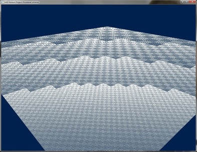
On the back of my approach to the patches and potentially not merging the changes; while testing the added detail on my planet I remembered a rather important fact which (due to the long time since reading up on terrain techniques) I had forgotten.
As great as the added detail is, having a large different in detail results in the dreaded cracking effect:
It is still possible that when the neighbouring faces have higher detail the cracks won’t be as obvious however without morphing, they are unavoidable and so there will at best be noticeable ”spots” which appear while traversing a planet.
Also, because of the precision being less towards the back of the z-buffer, the larger I make the view frustum, the more likely it is z-fighting will occur as rounding errors protrude. This means that I cannot simply extend the far plane to a large value but use a method that holds the distance information without drawing the objects incorrectly.
I’ve now over hauled my application so that I don’t waste valuable time scaling the Planets/Stars outside of the matrix multiplication as I figured out what was wrong initially.
I’ve also now introduced a second constant buffer to be used by the hull shader’s constant function. I initially tried to simply pass in a float, which through up dimension errors as apparently DirectX sees it at waste of time to send in anything smaller than 16 bytes to the GPU.
To get around this I send in an Matrix and then set the first member of the matrix to the amount I wish to tessellate by.
While implementing this, I realised I’d created a false memory of the working of the tessellation stage. It had been a while since I’d got it working and I haven’t really gone near it since. I’d done early experiments to try to get an understanding of what happens.
However, I’d been worried recently when considering my options for implementing CLOD. I’m confident I can get quadtree based level of detail implemented, but it’s those bastarding cracks that I was conscious of.
It was my belief that there was only two values for the tessellation factors, one for the inside of a patch and the other for the outside.
Instead, there are 2 values for the inside of the patch (controlling the amount of detail for the rows and columns) and 4 values for the outside of the patch (one for each of the edges).
It’s the latter feature that made me mentally jump for joy when I remembered, coming across it when implementing constant buffer controlled tessellation factor.
I was imagining I would have to create a difficult (and highly inefficient) algorithm that created extra patches designed to merge the main patches.
This will hopefully no longer be the case as I will instead only have to work out the detail of the neighbouring and then use a halfway value for the edges which will, in theory, close off those pesky cracks.
For example, if one patch has a tessellation value of 16.0 and it’s neighbouring patch has a value of 15.0, then their joining edge value will be set to (16.0 + 15.0) / 2.0 = 15.5.
One of the great advantages of the tessellation stages in DirectX is that the values don’t have to be integers, making merging different levels of detail a dream.
After an initial hiccup in the implementation that disguised itself as a NULL pointer dereference, I learnt more about the xna maths library. Part of the advantage is it’s use of the SIMD instruction set. However, it must be aligned appropriately in memory to allow the operations. Is was an alignment issue that was causing the error and not a NULL pointer.
The memory alignment is conveniently taken care of during compilation when variables are created as the compiler will force the memory allocated to be aligned. However, when memory is allocated at runtime from the heap, there is no guarantee that the memory will be aligned.
With the help of my honour’s supervisor, functions were created which would allocate aligned memory specifically for when a node is created so that it will be aligned.
Once this issue was fixed, I was able to concentrate back on the main problem at hand: Quadtree based LOD.
I had initially believed my implementation to be ready to work. However I soon learned it did not perform as expected. While it seemed to change between different sizes of patches, as intended, their positions where not quite so. Instead they took a spread out diagonal placing.
Looking at the code that places them I realised the error in my algorithm was creating unwanted values for the z placement. But I was able to rectify this and created the correct algorithm. Running this revealed that the offsets needed to be half the patch size. Once this was changed I was presented something painfully close to what I desire:
At first glance, it would appear to work exactly as intended: where detail would increase near the camera as it approached the surface. However, while this holds true to some extent, there is an artefact where detail in the corner at (1,0,1) increases in detail as the camera moves to the centre.
It’s also clear to me now that I’ll need to make a alteration to my plans for the edge detail, because a patch’s neighbour may have 2 or more patches of different size next to it. Therefore, the edge should be based on it’s parent’s detail, and the parent patch cares not for it’s children’s details.
On the back of my previous update, I believe the issue lies with me trying to compensate for the fact that the patch isn’t in the position it will be drawn. The patch is positioned along the face of a unit cube, however I’ll be wanting the distance from the camera to the patch based on where the patch will be once scaled to the size of the object. This would be an initial step as once turned into a sphere, the distance will be off as the camera approaches the corners.
However, I’m obviously not correctly calculating the distance. This was confirmed when I made the scale 1:1. So the distance is being based of a 2 x 2 patch even when scaled, which is why on a larger patch it doesn’t work correctly. However, it’s comforting to know it does work.
I was rather dismayed however when it was running very slow once more detail is added. I tried lowering this by lowering the detail per patch however this didn’t change the frame rate. I shamefully realised I was printing each of the patches position per frame. A foolish mistake and, as expected, once this was removed, the application ran silky smooth.
It’s also clear I can have control over how many levels of detail there are. Larger planets will need more levels than small ones. As they’re multiples of halves I could test whether the patch size was less than or equal to the limit.
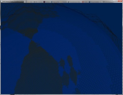
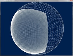
So I’m back to my cube to spheres but this time with a new look:
As expected, the LOD doesn’t run fully when approaching the “corners” of the sphere, to the point where detail actually decreases as you reach them.
The next step to rectify this is to base it now on the patch’s new spherical position.
This still won’t be 100% correct as the elevated vertices will still be based on their flat patches, so if the camera is flying over the top of the mountains, the LOD won’t be as high as if the camera was flying through the mountains.
Another issue that’s arisen, though one which had occurred with my split face implementation, is that the higher LOD drop the frame rate dramatically.
As I expected, dropping the detail of each patch didn’t fix the issue, which confirmed my suspicion that the issue instead lies within the fractal calculations as each patch is recalculating the fBm. This obviously is inefficient and so I will have to work out a way of calculating the fBm for the object which the shader can then use.
The most obvious solution is to pre calculate the fBm on the CPU into a buffer which the shader can access. However, this would create a catch22 situation between the limited detail based on the size of the buffer as well as how much memory the buffer would take up, as the project is for multiple planetary bodies.
I now can record my application straight off the computer (so no more unsteady hands)
I had issue compressing the video however and Tumblr didn’t really help. So I’ll be posting my videos onto vimeo for the time being. This video shows how my application converts my cube into a sphere
As my planet was struggling to render in real-time I decided it was time to look into using a texture to relieve some of the computational stress in calculating the fractal Brownian motion.
I knew going into creating the texture that there would be limitations:
- The texture can’t be too large as memory is limited
- When using the texture as a basis, rounding errors will be immediately prominent as no more detail can retrieved.
However, before I even got to these issues, I hit implementation problems. Firstly I had to re-familiarise myself with DirectX11’s API for textures. Which took a good while; in it’s attempt to be diverse and efficient it’s really convoluted in what you need to set up.
It’s then not clear exactly how you fill a texture. I first shot at creating a 1080x1080 texture. This was very quickly shot down by the compiler when it informed me I’d occurred a stack overflow. So I decided to start off with a 256x256 texture.
I then ran into problems when sampling the texture: it only appeared to sample the first row of the texture. I soon managed to get it to render more of the texture, however it was clear that it still wasn’t completely correct - it didn’t appear to render the entire texture, just a section. Tests on this were inconclusive in finding out exactly what was being rendered.
These issues, and the likely hood that it would be more of a hassle to fix them and implement the textures as desired, combined with the inevitable problems that would have come after led me to the decision to revert back to calculating the fBm in the shader and instead focusing on trying to get it to run better.
One reason for it running slow is that patches are being rendered even if they’re not viewable, I’ve yet to make them clip. This was particularly a problem when my planet was relatively small as the quadtrees were splitting up on the otherside of the sphere. So when I drastically enlarged my planet, it actually managed to run smoother.
I’ve also managed to implement the distance based LOD for the fBm, where less octaves are used when far away. This makes the transition a lot smoother than when implemented through the vertices.
I’ve also improved the aesthetics in preparation for comparative images in my study. I’m still unable to get the correct transformed normals for the planet so the lighting is currently using incorrect normals. However, because I had to pass in a matrix for a constant buffer to be relevant, I’ve not been able to take advantage of it to pass in data not only for the tessellation patch detail but also the camera position and it’s look vector. Which was used for the fBm LOD and specular lighting. I use more detail in the pixel shader as it’s possible to feign more land mass.
My noise issue is solved.
Since it’s first implementation into my honours project, the noise hasn’t worked. I wasn’t sure why, as the implementation had worked in my previous procedural project. However, it wasn’t a large issue at first, as the other features had to implemented.
However the cause of the problem lingered. Recently however, I went over my 3rd year project and realised that while the shader was the same, the implementation in fact wasn’t. That project used the effects framework, while I’m using DirectX’s API. I then wondered about the usage of globals in the 5.0 shader model.
Sure enough, you cannot simply declare a variable in global scope, it must be static. However I knew before even doing this that it would be hazardous for performance. However, to check whether this was the issue I proceeded with using a static array for the hash values of my noise.
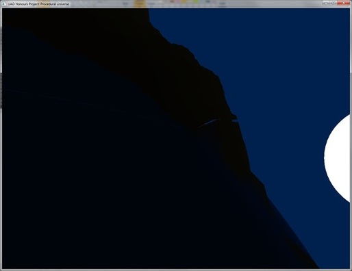
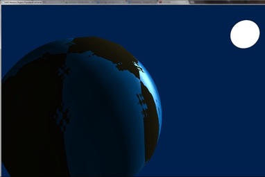
Sure enough, success:This also makes the planet a little tidier when getting near the coasts and even allows for smaller islands to appear that wouldn’t have if only based off the vertices.
Here is a shot showing the improved lighting:
As expected, the LOD doesn’t run fully when approaching the “corners” of the sphere, to the point where detail actually decreases as you reach them.
The next step to rectify this is to base it now on the patch’s new spherical position.
This still won’t be 100% correct as the elevated vertices will still be based on their flat patches, so if the camera is flying over the top of the mountains, the LOD won’t be as high as if the camera was flying through the mountains.
Another issue that’s arisen, though one which had occurred with my split face implementation, is that the higher LOD drop the frame rate dramatically.
As I expected, dropping the detail of each patch didn’t fix the issue, which confirmed my suspicion that the issue instead lies within the fractal calculations as each patch is recalculating the fBm. This obviously is inefficient and so I will have to work out a way of calculating the fBm for the object which the shader can then use.
The most obvious solution is to pre calculate the fBm on the CPU into a buffer which the shader can access. However, this would create a catch22 situation between the limited detail based on the size of the buffer as well as how much memory the buffer would take up, as the project is for multiple planetary bodies.
I now can record my application straight off the computer (so no more unsteady hands)
I had issue compressing the video however and Tumblr didn’t really help. So I’ll be posting my videos onto vimeo for the time being. This video shows how my application converts my cube into a sphere
As my planet was struggling to render in real-time I decided it was time to look into using a texture to relieve some of the computational stress in calculating the fractal Brownian motion.
I knew going into creating the texture that there would be limitations:
- The texture can’t be too large as memory is limited
- When using the texture as a basis, rounding errors will be immediately prominent as no more detail can retrieved.
However, before I even got to these issues, I hit implementation problems. Firstly I had to re-familiarise myself with DirectX11’s API for textures. Which took a good while; in it’s attempt to be diverse and efficient it’s really convoluted in what you need to set up.
It’s then not clear exactly how you fill a texture. I first shot at creating a 1080x1080 texture. This was very quickly shot down by the compiler when it informed me I’d occurred a stack overflow. So I decided to start off with a 256x256 texture.
I then ran into problems when sampling the texture: it only appeared to sample the first row of the texture. I soon managed to get it to render more of the texture, however it was clear that it still wasn’t completely correct - it didn’t appear to render the entire texture, just a section. Tests on this were inconclusive in finding out exactly what was being rendered.
These issues, and the likely hood that it would be more of a hassle to fix them and implement the textures as desired, combined with the inevitable problems that would have come after led me to the decision to revert back to calculating the fBm in the shader and instead focusing on trying to get it to run better.
One reason for it running slow is that patches are being rendered even if they’re not viewable, I’ve yet to make them clip. This was particularly a problem when my planet was relatively small as the quadtrees were splitting up on the otherside of the sphere. So when I drastically enlarged my planet, it actually managed to run smoother.
I’ve also managed to implement the distance based LOD for the fBm, where less octaves are used when far away. This makes the transition a lot smoother than when implemented through the vertices.
I’ve also improved the aesthetics in preparation for comparative images in my study. I’m still unable to get the correct transformed normals for the planet so the lighting is currently using incorrect normals. However, because I had to pass in a matrix for a constant buffer to be relevant, I’ve not been able to take advantage of it to pass in data not only for the tessellation patch detail but also the camera position and it’s look vector. Which was used for the fBm LOD and specular lighting. I use more detail in the pixel shader as it’s possible to feign more land mass.
My noise issue is solved.
Since it’s first implementation into my honours project, the noise hasn’t worked. I wasn’t sure why, as the implementation had worked in my previous procedural project. However, it wasn’t a large issue at first, as the other features had to implemented.
However the cause of the problem lingered. Recently however, I went over my 3rd year project and realised that while the shader was the same, the implementation in fact wasn’t. That project used the effects framework, while I’m using DirectX’s API. I then wondered about the usage of globals in the 5.0 shader model.
Sure enough, you cannot simply declare a variable in global scope, it must be static. However I knew before even doing this that it would be hazardous for performance. However, to check whether this was the issue I proceeded with using a static array for the hash values of my noise.
Sure enough, success:This also makes the planet a little tidier when getting near the coasts and even allows for smaller islands to appear that wouldn’t have if only based off the vertices.
Here is a shot showing the improved lighting:
My noise issue is solved.
Since it’s first implementation into my honours project, the noise hasn’t worked. I wasn’t sure why, as the implementation had worked in my previous procedural project. However, it wasn’t a large issue at first, as the other features had to implemented.
However the cause of the problem lingered. Recently however, I went over my 3rd year project and realised that while the shader was the same, the implementation in fact wasn’t. That project used the effects framework, while I’m using DirectX’s API. I then wondered about the usage of globals in the 5.0 shader model.
Sure enough, you cannot simply declare a variable in global scope, it must be static. However I knew before even doing this that it would be hazardous for performance. However, to check whether this was the issue I proceeded with using a static array for the hash values of my noise.
Sure enough, success:
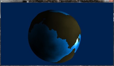
However I now needed to find a way of having a static array to read from that isn’t in the global scope. The two obvious solutions are either using a constant buffer or a texture buffer. A constant buffer is the option I went with because, besides being easier to implement, constant buffers are also optimised for GPU resource updating, as the buffer will only be updated when ever the noise permutation is generated (typically once) it should run rather nice.
And run rather nice it did.
To my surprise, it actually runs better than it had been doing! Moving the permutation array out of the shader and into my application also allowed me to have some fun with generating different Earth-like planets.
I imagined that when I recreated the array, it would slow down the application. Again to my surprise, it regenerates at an exceptionally fast pace. As shown in my video
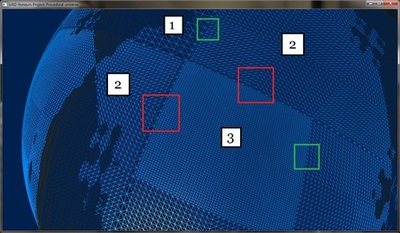
Fixing the noise leaves only one more glaring issue: Those pesky cracks.
I attempted to alleviate them with a method I came up with. But I soon realised that this method was only working for specific patches and didn’t take into account that there are other neighbouring patches which may have differing levels of detail. As shown in this image:
Where the green boxes are where there are no possible cracks, but the red boxes are where cracks can, and bloody well do, appear.
It’s more than possible to remove the cracks, I know how I could do it. However, I wish to come up with a smarter method which sorts it and still runs smoothly.
While I knew in my head I’d be able to come up with a simple solution to merging the patches, I didn’t imagine I’d be able to solve it with such little effort, and so soon after fixing my noise issues too!
The cracks aren’t 100% gone. But they are drastically reduced, enough for this project.
I wanted to take advantage of DirectX 11’s tessellation stage’s feature where you can assign a different amount of detail for a tessellated patch’s edges to the centre detail.
So I knew it should be possible to make the edges of my level of detail seamless.
My first attempt was where I acknowledged that each level of detail essentially doubles the edge detail. So if an edge had 32 vertices, the next level of detail would make the edge have 64 vertices. As the two neighbouring patches aren’t connected, these edges are opened up to cracks. So I simply came up with an algorithm that halved the outer edges of the child patches.
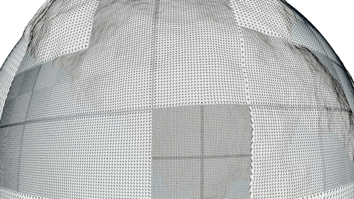
However, this only solved the issue for the “best case scenario” and I’d overlooked the typical scenario. As shown in a previous post, there were moments where a patch may have neighbouring patches of different levels of detail. As each edge can only have a single value of detail, I knew it was down to the child patches to make the edges seamless.
Of course, merging LOD is a solved issue, however I wished to come up with a less complex method that worked with my current set up. I wanted to try to do it without having to traverse my quadtree structure more than once, as that would considerably slow down my application.
Fortunately, I managed to do just that.
As the picture shows, the edges of each patch merge seamlessly into the surrounding patches.
However, this technique is limited. To conserve the amount of vertices on an edge means that eventually a patch edge will have a detail of 1 (the smallest possible) and so further levels of detail with result in the possibility of cracks. However, they’re drastically reduced in size and much rarer.
To maximize the guaranteed crack free levels of detail, the edge is set to have the maximum number of vertices (64) which means that there can be up to 7 seamless levels of detail.
The pictures below aim to give a sense of the difference this merging technique makes. The only technical thing really left to do is implement a clipping technique that reduces the amount of patches rendered, namely frustum culling.


It seems to be the case that, the closer to a deadline, the more work I manage to produce. It’s not a pressure thing, I just seem to manage to produce more work as the deadline approaches.
This is problematic when trying to write up on what I’ve produced when I keep on producing. Still, what I have produced has certainly sexed up my application.
The first thing I managed to do was implement a skybox to fill out the dull darkness. Had I been able to do implement some of the technologies earlier on, and had more time to implement more pretty shit, I would have had procedurally positioned solar systems, which is similar to how the skybox images were created.
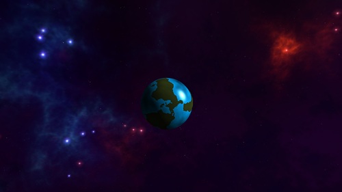
The second thing I managed was to implement more complex lighting, based on the vertex normal. The issue I had with this was I didn’t know where the neighbouring vertices are. But I then realised I could “guess”.
I basically create two more vertex positions perpendicular to the original vertex, and work out their positions on the planet. From this I can calculate the normal for the main vertex.
I basically create two more vertex positions perpendicular to the original vertex, and work out their positions on the planet. From this I can calculate the normal for the main vertex.
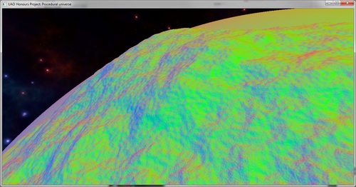
While this creates much more realistic terrain, basing it on the vertex normal (as opposed to in the pixel shader) creates some artefacts, including emphasising the patch seams
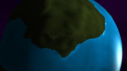

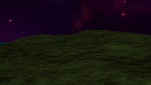
I simply haven’t the time to fix these issues; if I calculated the normal based on pixel position, the vertex position wouldn’t hinder the shading. However, to do this, I’d need to pass in the cube’s world matrix. This would be maddening to do for every pixel, instead I’d have to use a constant buffer. However, to do this I’d need to allocate aligned memory.
While my land looks better than the totally flat appearance when rendered with spherical normals, it’s now more noticeably unearth-like, it looks really rounded.
So I decided to try out different fractal terrain techniques to try and find a better terrain.
The first was a heterogeneous multifractal. This made the terrain more jagged inland, and smoothed out to the end. However, it needed to be lowered as the coast was too smooth. similarly, the mountains are too jagged.
The next was a ridged multifractal (the same as used for creating the nebulas in the skybox). This made more mountain-like structures, however, the land looks more like sand dunes than rock and the coast line doesn’t look correct.
I decided instead to use the original fBm but with some form of ridges. They’re not quite mountains, as they run at the same height, but they do look like mountain ranges and less like sand dunes.
I’m not 100% happy with it, however I really need to crack on with my dissertation. Although not before I implement better clipping techniques!
For I can’t really do my results section when my application doesn’t run as well as it should do.
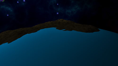
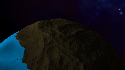
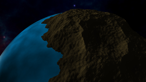
 RSS Feed